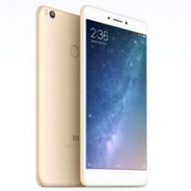
Recently, Huawei launched the Honor 8X. This phone features a 6.5-inch screen with a screen-to-body ratio of up to 91% and is powered by a HiSilicon Kirin 710 processor. Now, we will take apart the Honor 8X to explore its internal structure and workmanship.
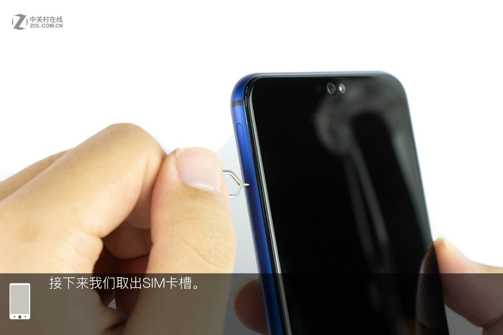
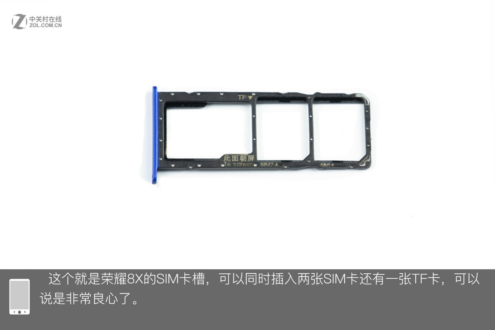
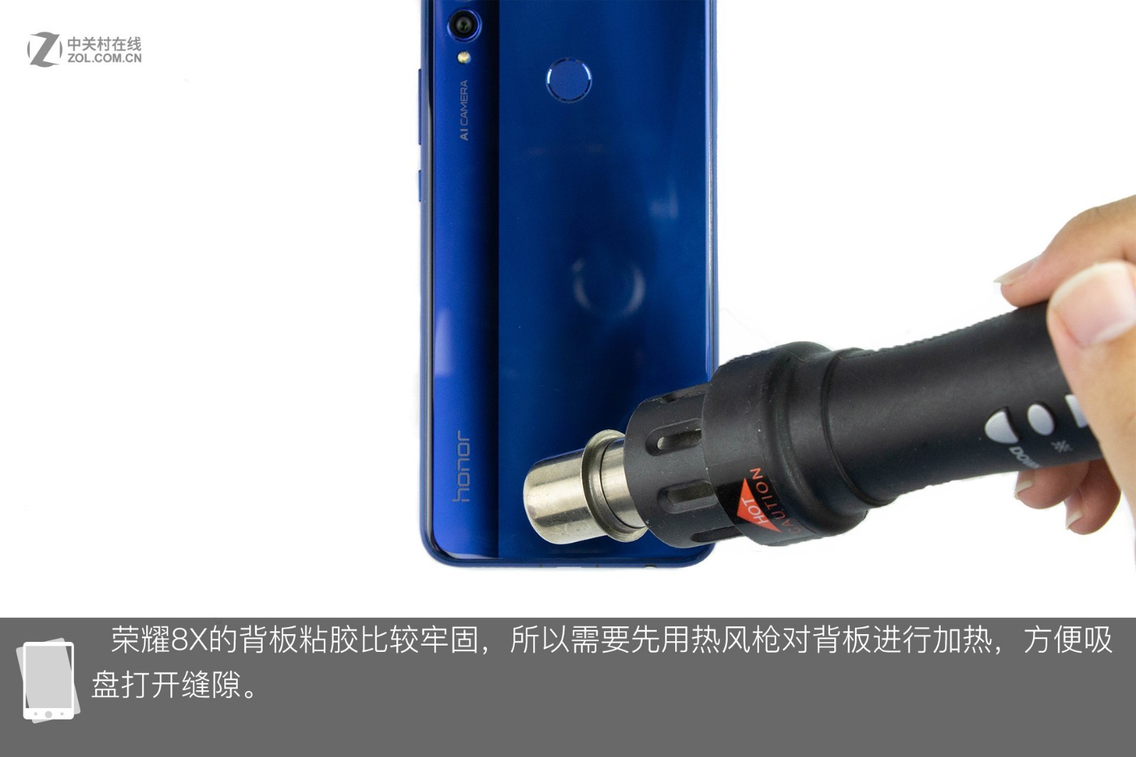
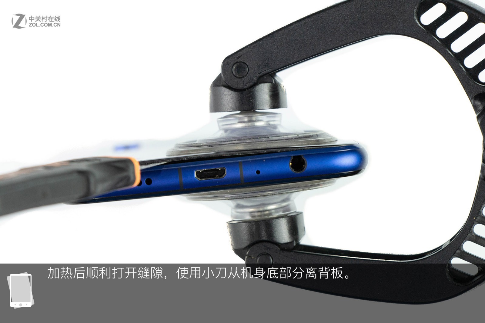
First, remove the SIM card tray. Its SIM card tray can hold two SIM cards and one TF card simultaneously. Since the back cover is tightly bonded to the body, I need to heat it with a heat gun first. Then, use a suction cup to create a gap between the back cover and the body, and use a pick to open the back cover.
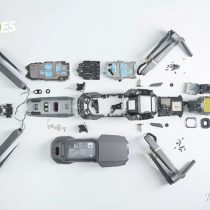
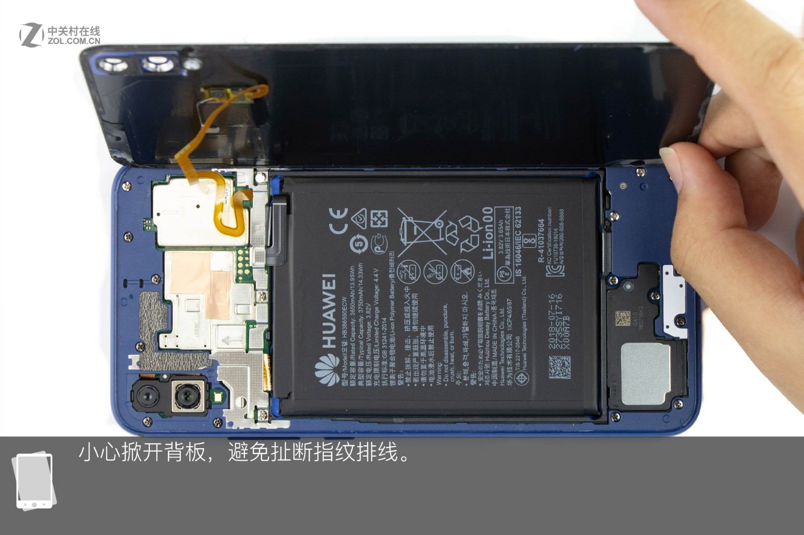
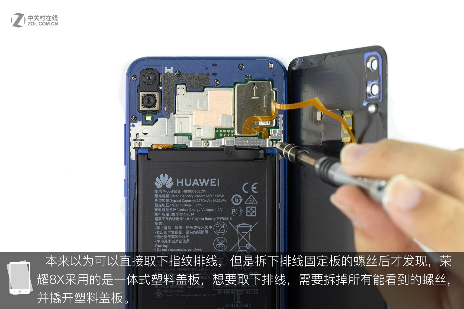
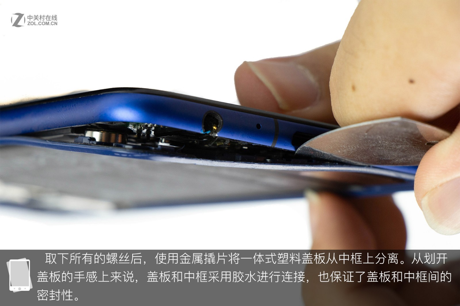
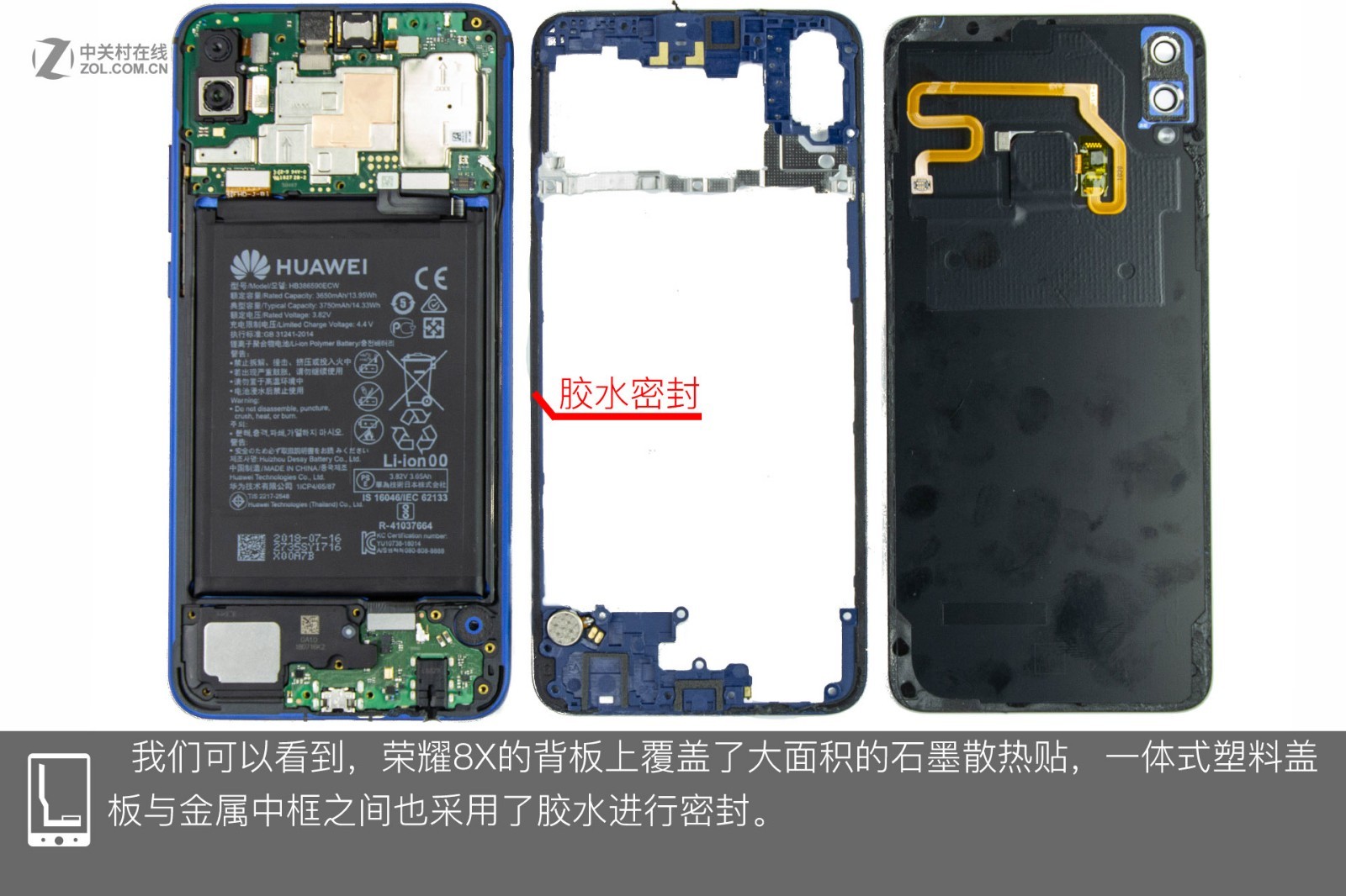
Now, open the back cover and do not disconnect the fingerprint sensor cable. I planned to remove the fingerprint sensor cable directly, but it was unsuccessful. After removing the screws that secure the cable, I found that the phone uses an integrated plastic panel design, so I must first remove all visible screws, then remove the plastic panel. After removing all visible screws, use a metal clip to separate the plastic panel from the middle frame. The panel appears to be glued to the middle frame, a design that helps enhance the seal between the panel and the middle frame.
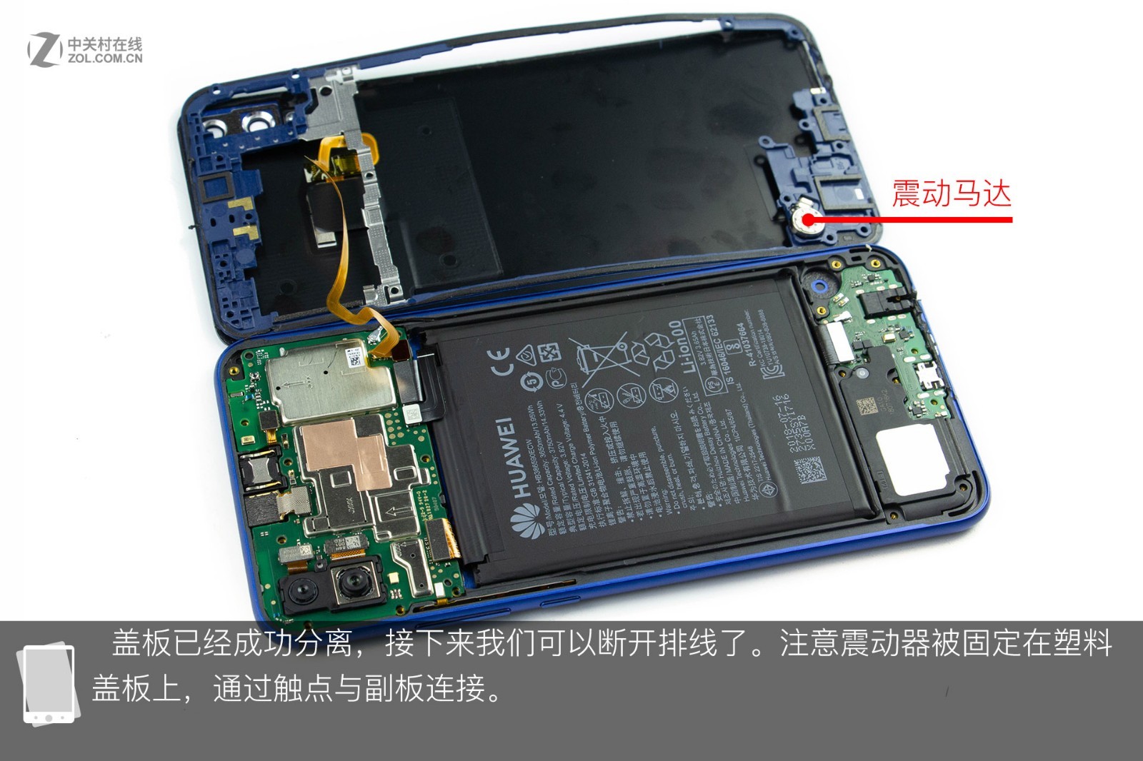
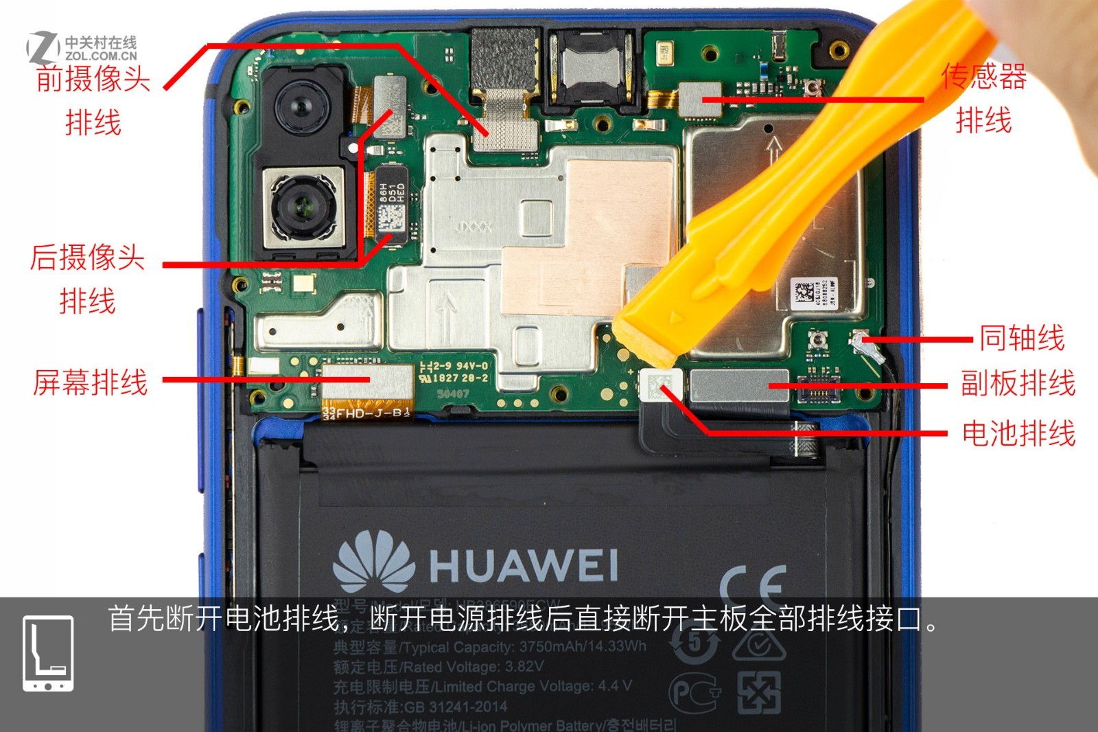
The back cover is covered with multiple graphite stickers. Glue has also been applied between the plastic plate and the metal middle frame to enhance sealing. First, disconnect the battery connector, and then disconnect all other cables from the motherboard.
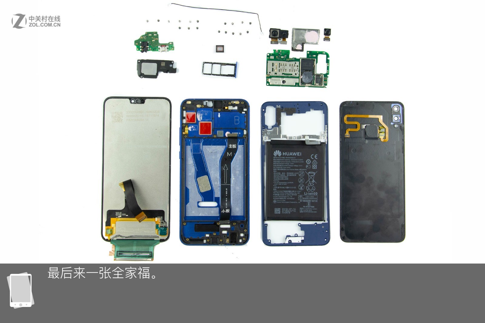
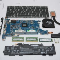
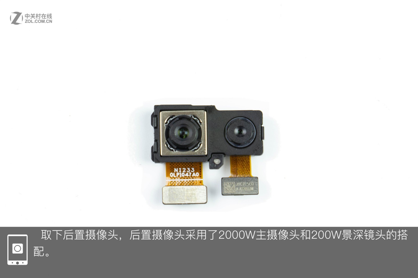
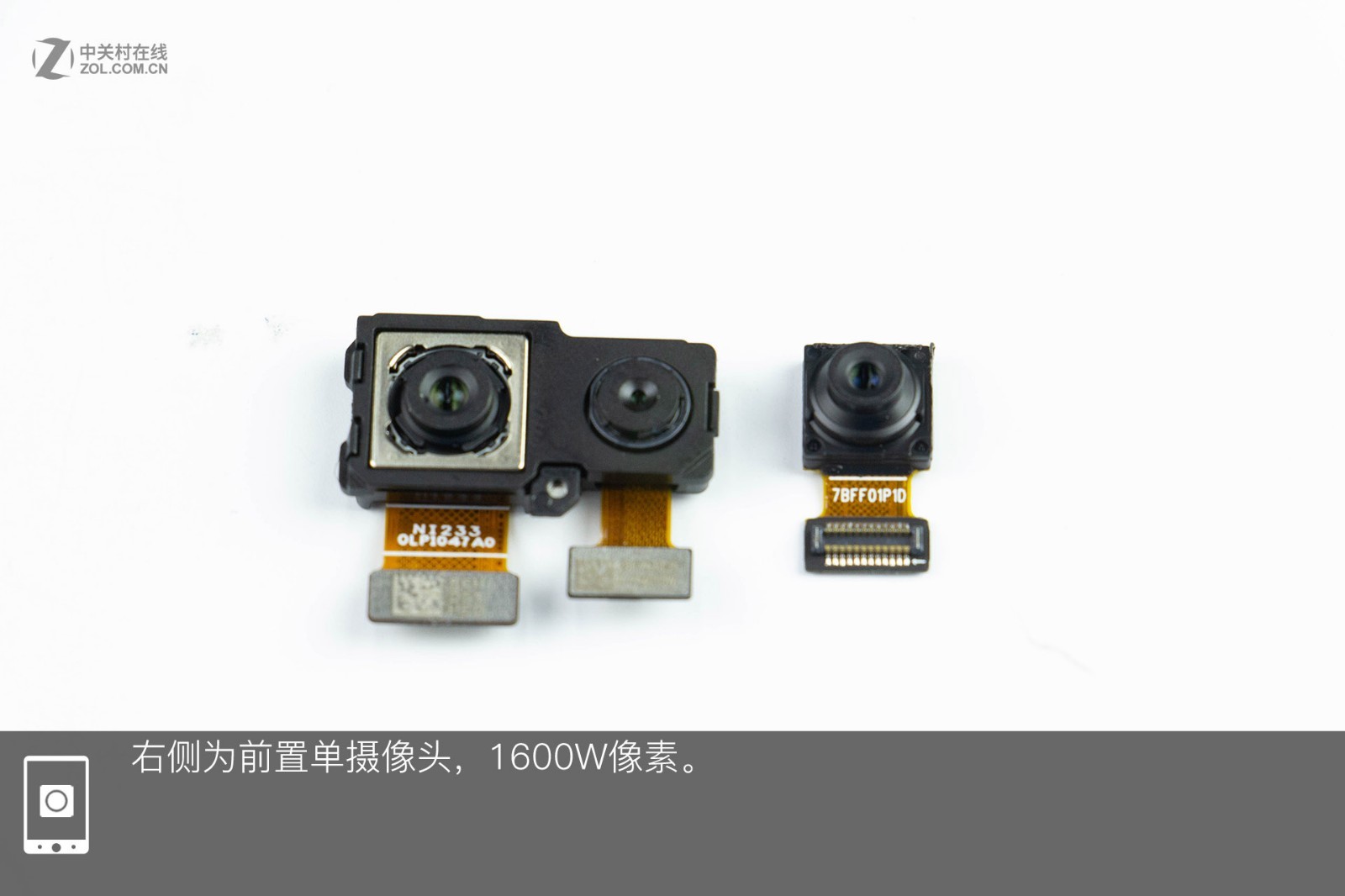
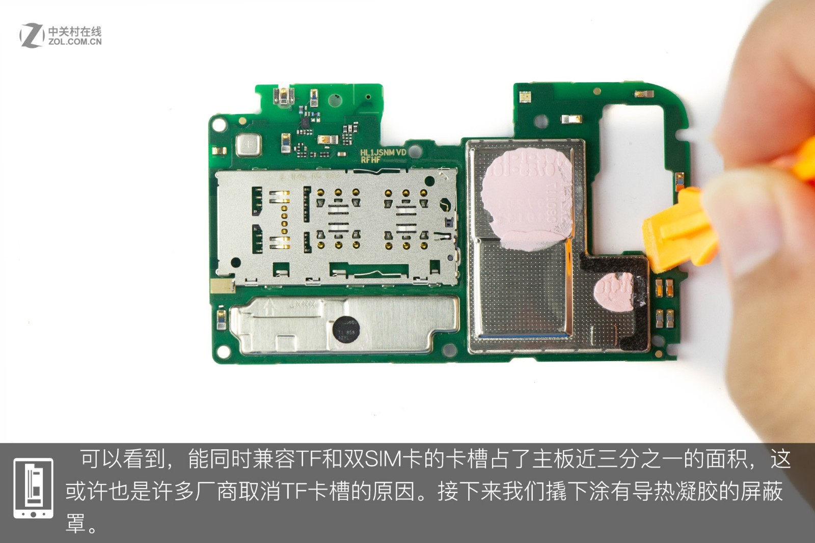
The dual rear camera module includes a 20MP main lens and a 2MP depth lens, while the 16MP front camera is located on the right. The SIM card tray occupies nearly one-third of the motherboard and can hold two SIM cards and one TF card. Perhaps because of this, many manufacturers choose to cancel the TF card slot. Next, I will remove the metal shield, which is covered with thermal grease.
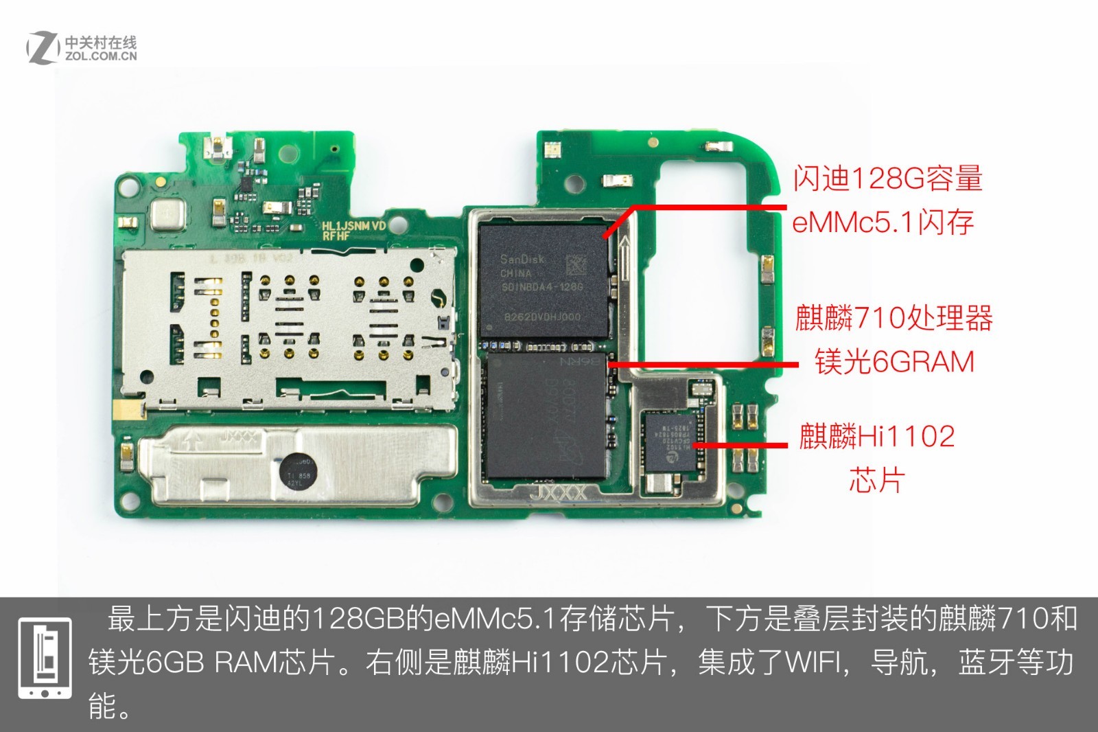
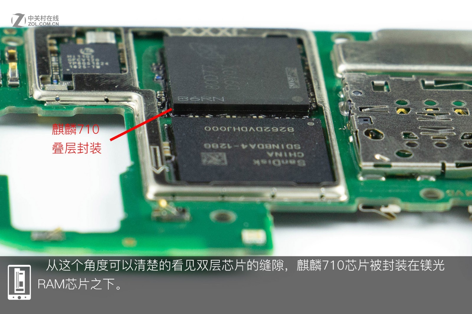
The 128GB eMMC 5.1 memory chip from SanDisk is placed on top, and the Kirin 710 chip and the 6GB RAM chip from Micron are stacked below it. The Kirin Hi1102 chip with Wi-Fi, navigation, and Bluetooth functions is on the right. The Kirin 710 chip is placed under the RAM chip. Disconnect the cable and coaxial cable from the sub-board, then remove the sub-board.
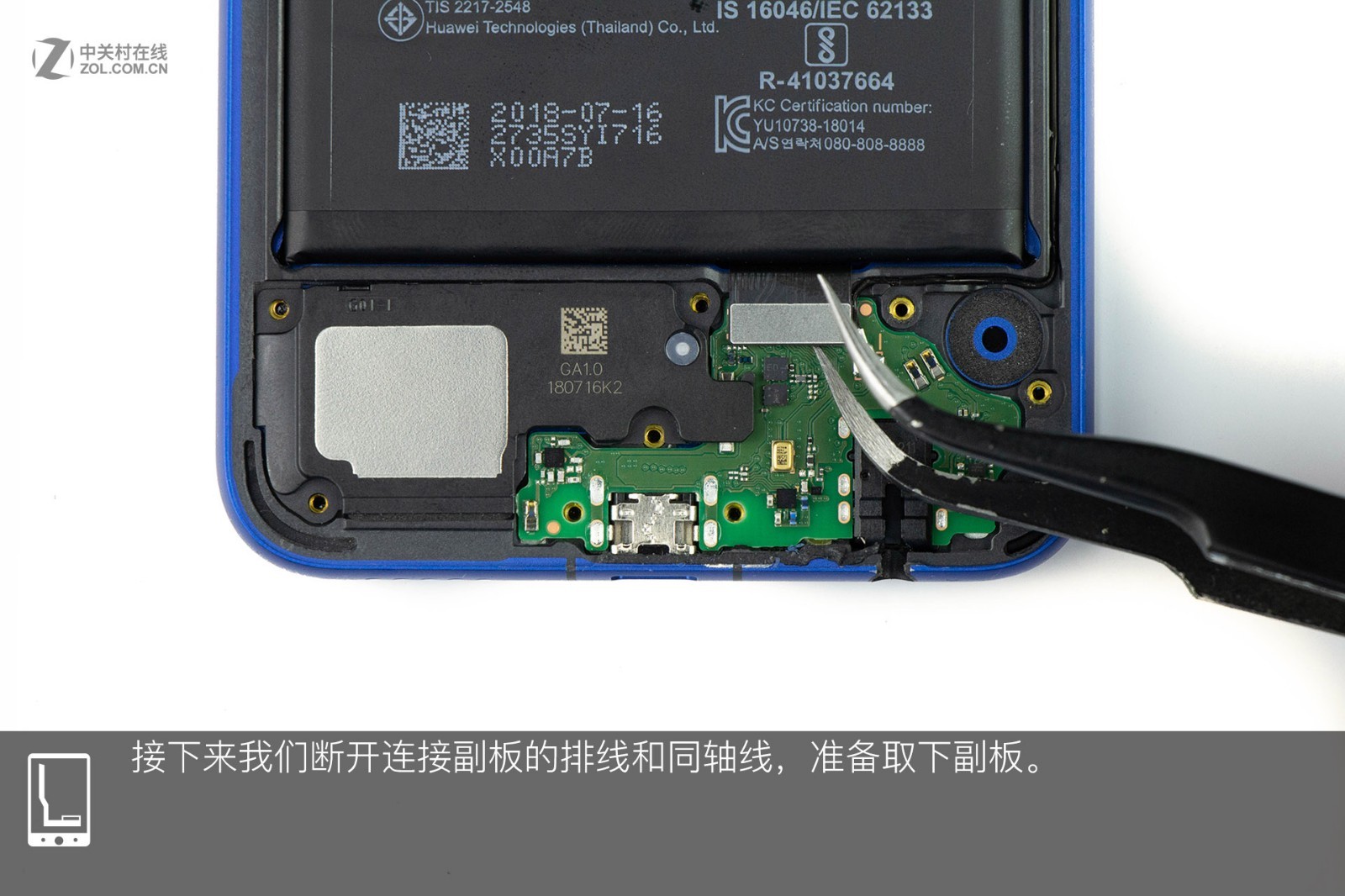
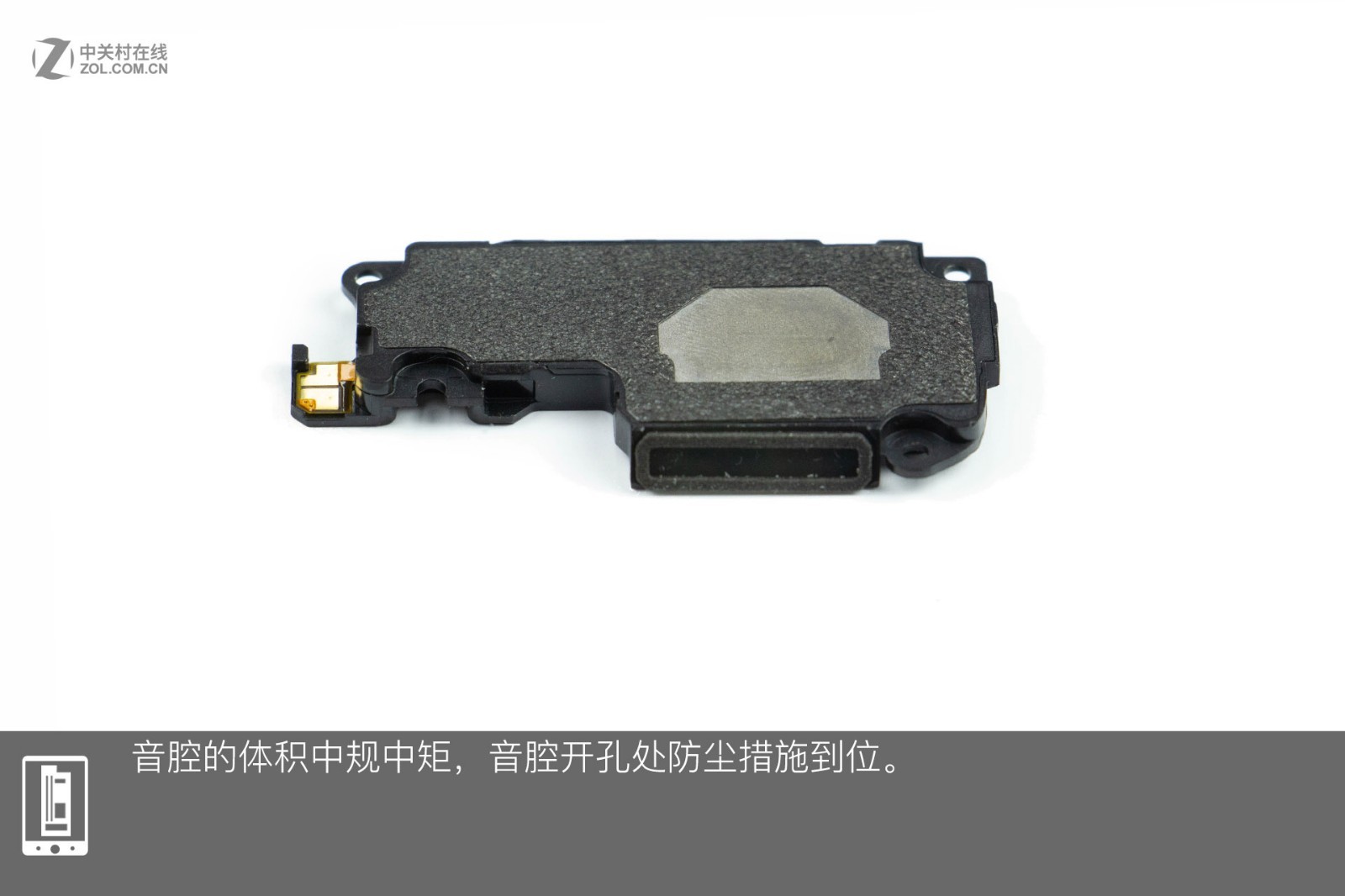
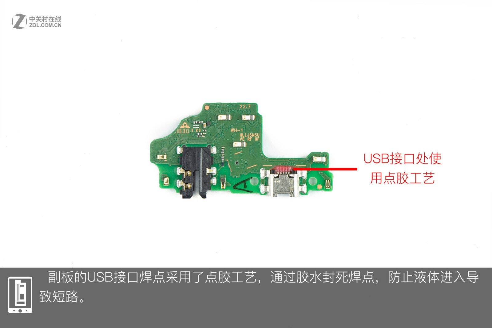
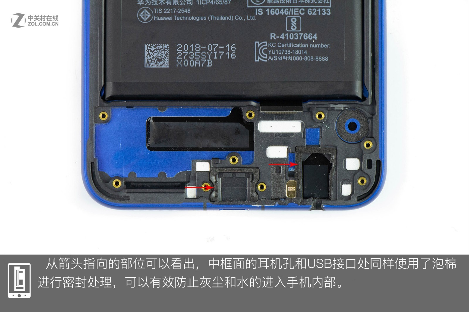
This is its sound chamber. The USB port is soldered onto the sub-board. Both the headphone jack and USB port use foam seals, which can effectively block dust and liquids from entering the phone.
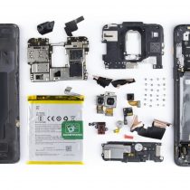
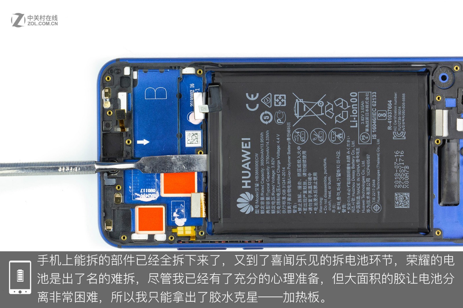
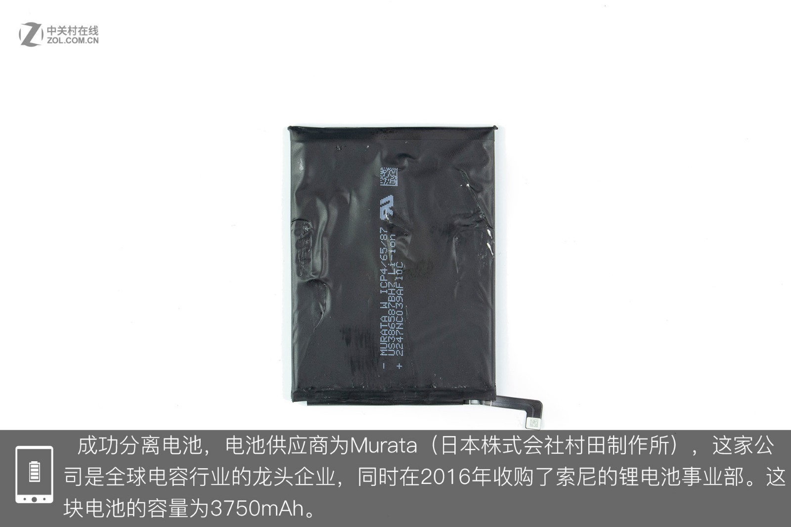
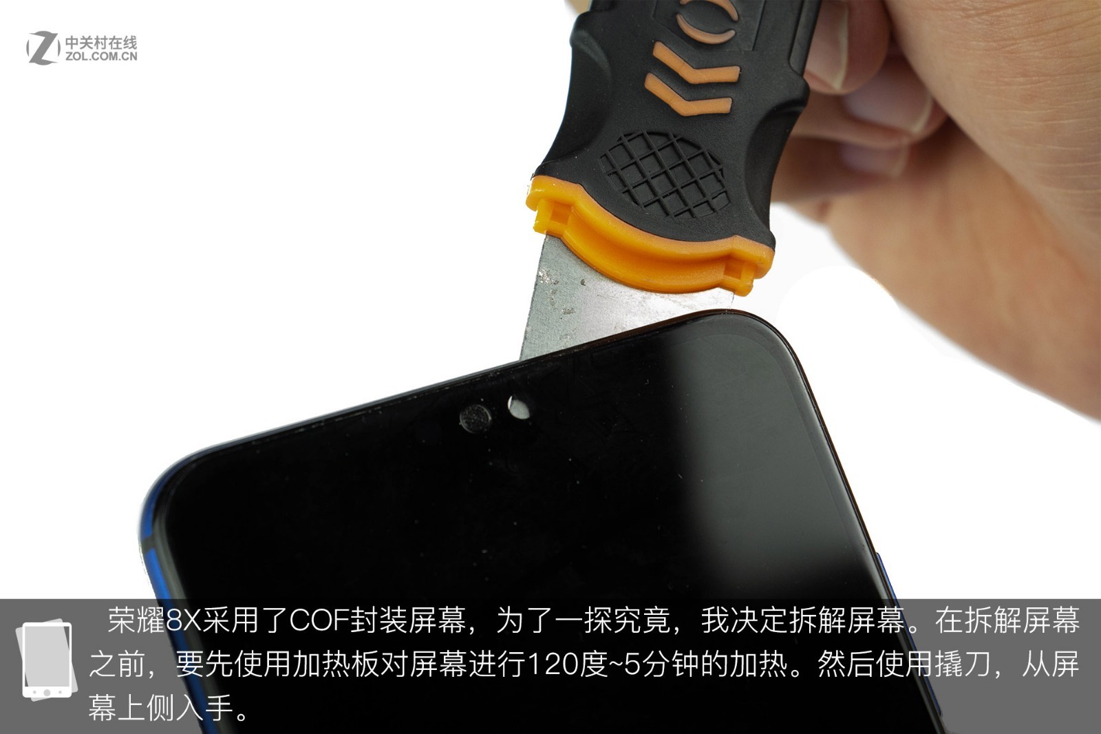
Next, I need to remove the battery. As we all know, removing a battery is not easy. I found that a large amount of glue was attached to the battery, making the removal process even more difficult. Therefore, I had to use a heating plate. Now, I have successfully removed the battery. The battery was manufactured by Murata and has a capacity of 3750mAh. Murata is a leading capacitor manufacturer and acquired Sony’s lithium battery business division in 2016. To explore the mysteries of COF technology, I decided to remove the screen. I heated the screen at 120°C for five minutes, then removed it with a blade.
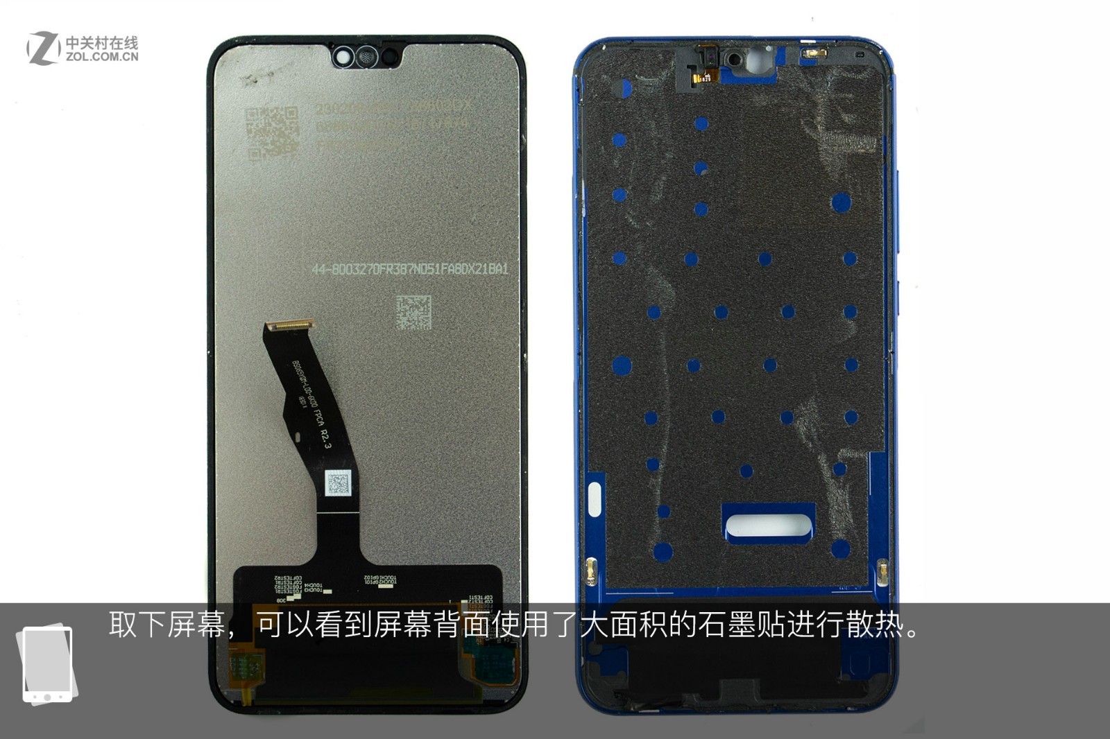
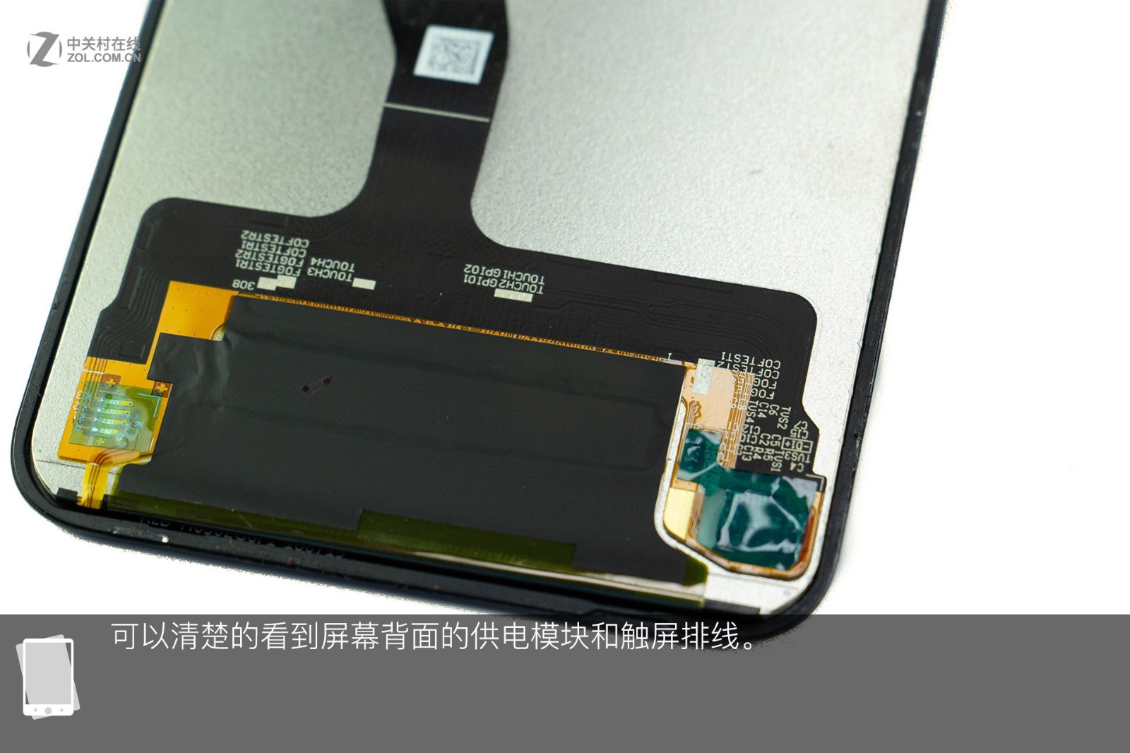
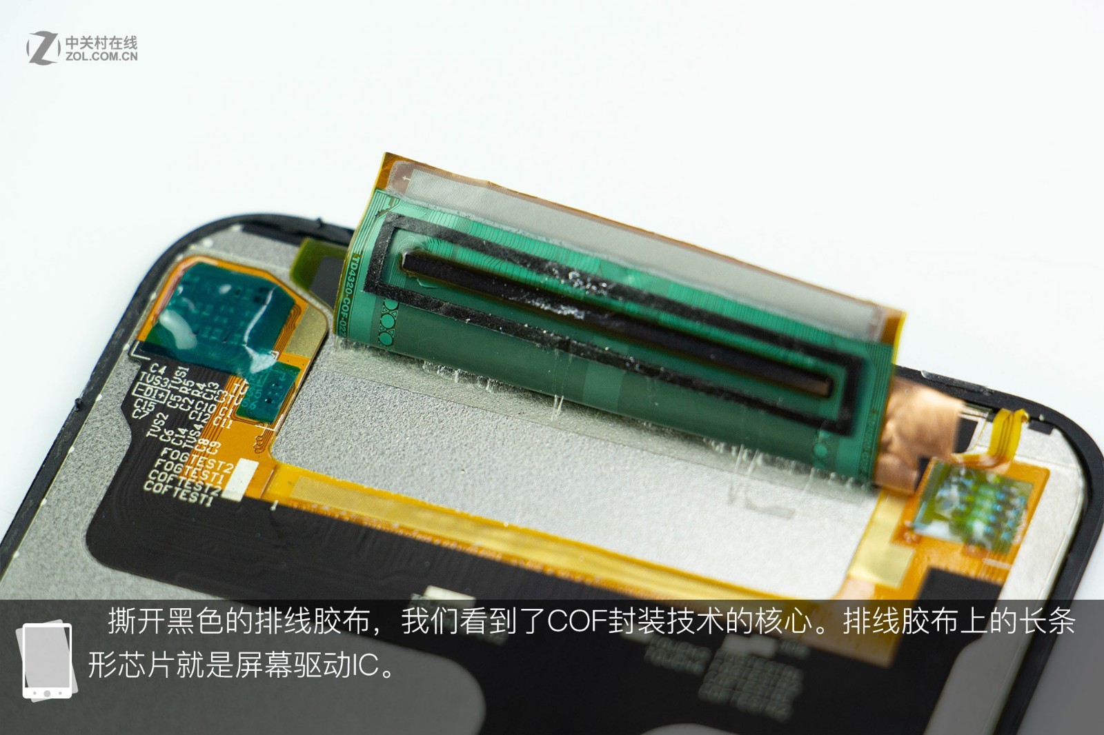
After removing the screen, we can see that many graphite stickers have been applied to the back for heat dissipation. The power module and touchscreen flex cable are visible on the back of the screen. After peeling off the black flex cable tape, the screen driver IC is visible, which is the chip on the black tape.