Dell LaptopDell Latitude E6410
Dell Latitude E6410 Disassembly and SSD, RAM, HDD Upgrade Options
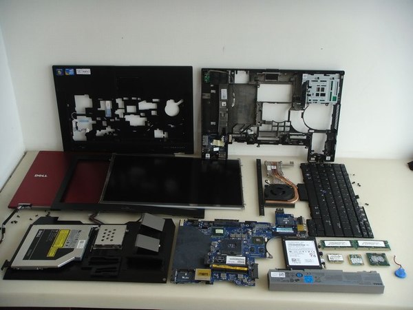
In this guide, I’ll explain how to disassemble the Dell Latitude E6410 to remove the bottom case, hard drive, DVD drive, RAM, keyboard, palm rest, touchpad, wireless card, heat sink, cooling fan, camera, screen, LCD hinge, speaker and motherboard.
Want to stay connected to MyFixGuide.com? Follow us on Facebook to check out the latest teardown news.
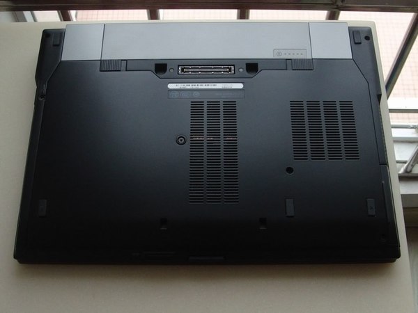
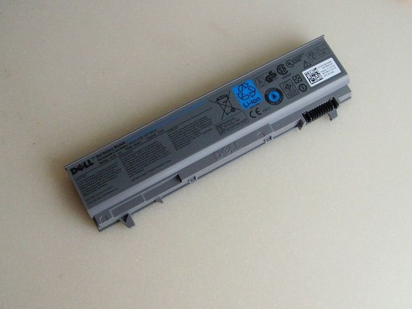
Unlock two latches and remove the battery.
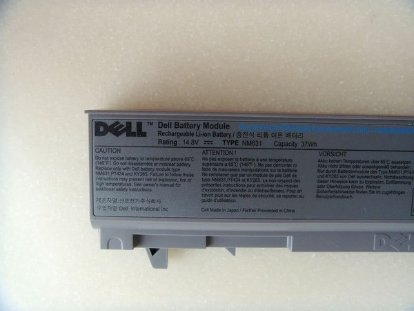
It features a 14.8v, 37wh Li-ion battery. Dell P/N: NM631.
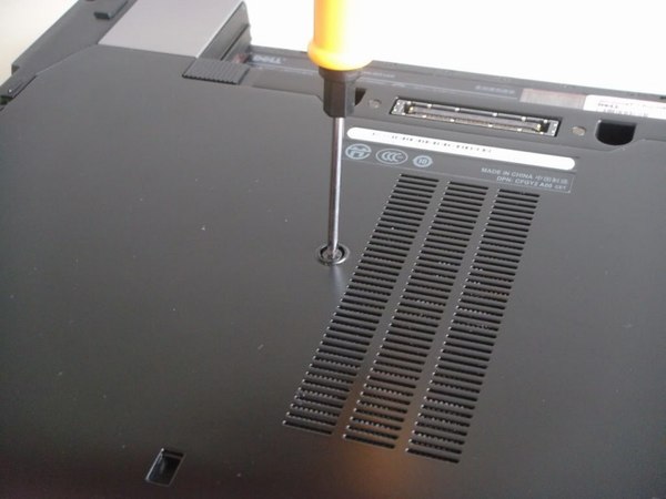
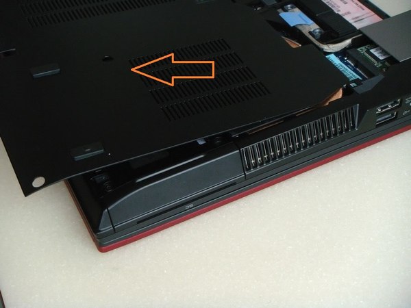
Remove the screws securing the back cover.
Now you can get access to the RAM, hard drive, wireless card, heat sink, and cooling fan.
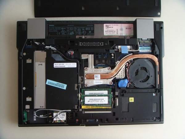
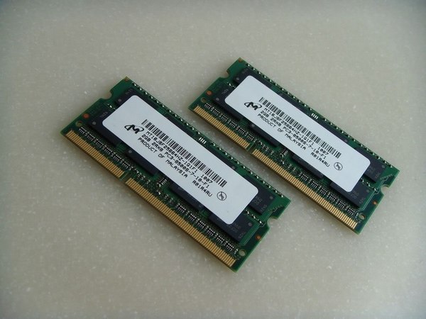
The laptop has two Micron 2GB memories installed.
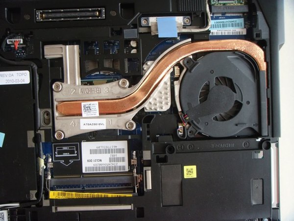
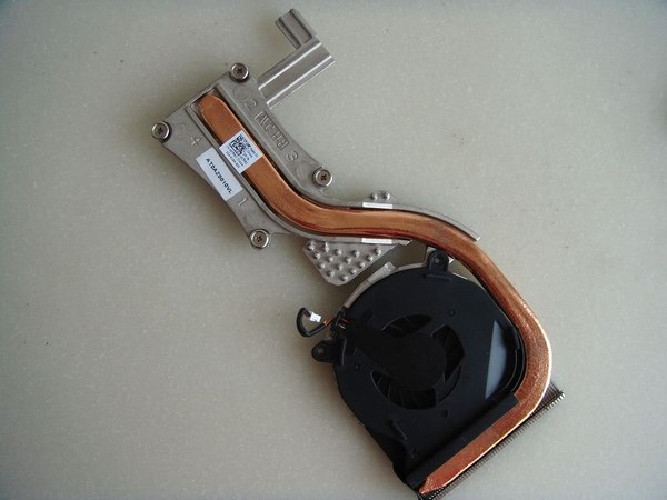
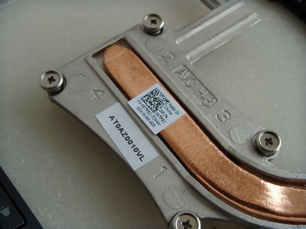
Loosen four screws securing the heat sink. You can remove it.
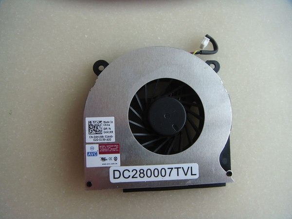
Dell Latitude E6410 cooling fan P/N: 04H1RR
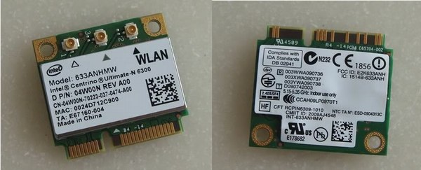
Disconnect two antennas and remove the screw securing the card.
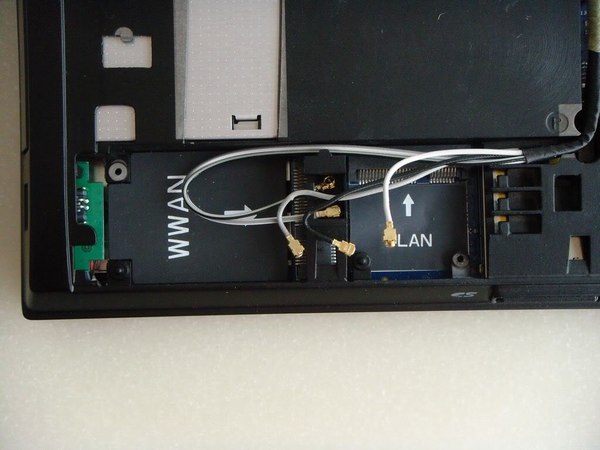
Intel® Centrino® Ultimate-N 6300 wireless card. Dell P/N: 04W00N.
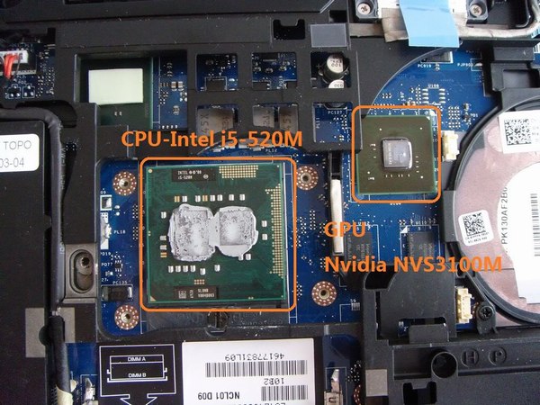
Dell Latitude E6410 CPU and GPU
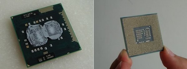
Intel® Core™ i5-520M processor (3M Cache, 2.40 GHz)
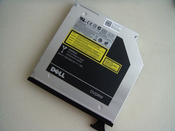
Remove this screw and pull out the switch. You can pull out the DVD drive.
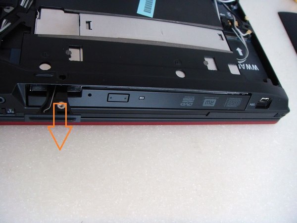
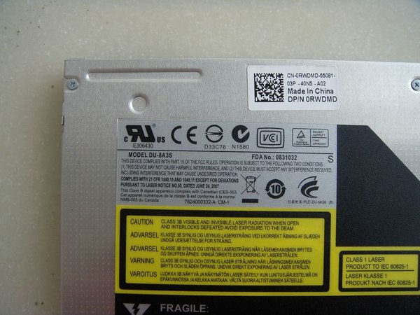
The laptop comes with a 9.5mm ultra-thin optical drive.
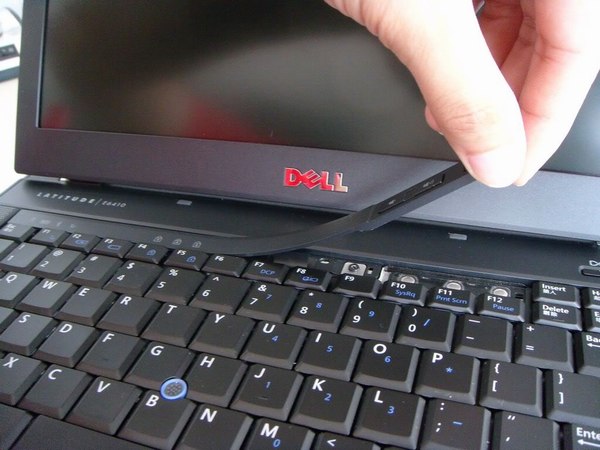
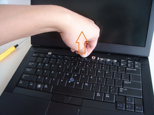
Turn over your laptop. Lift up the keyboard bezel and remove it.
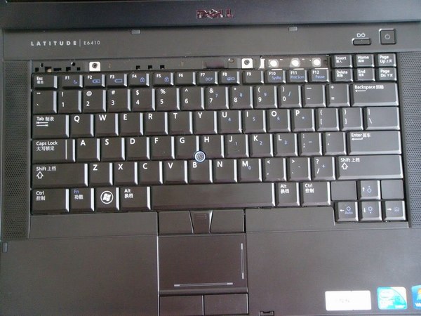
Remove two screws securing the keyboard.
Place the keyboard on the palm rest and disconnect the keyboard cable and backlit cable.
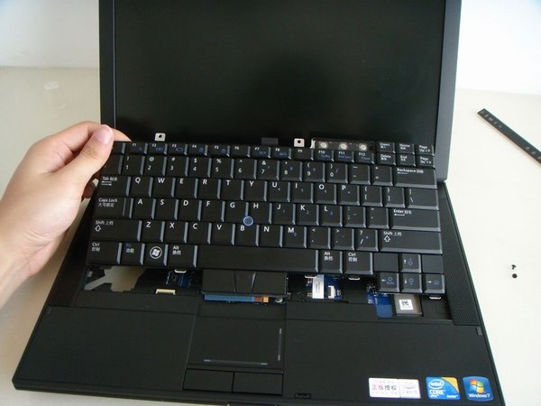
The keyboard has been removed.
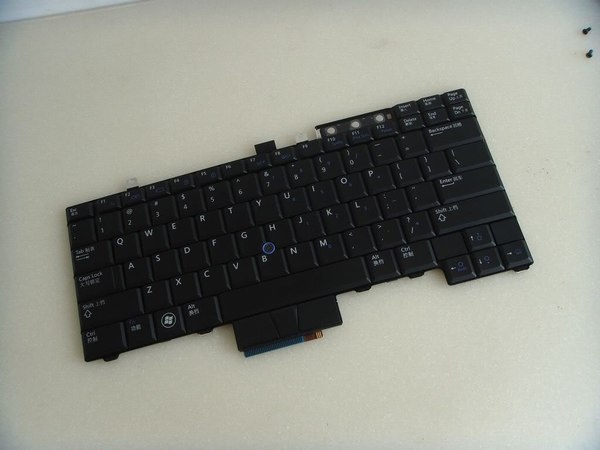
Remove the screw securing the silver cover.
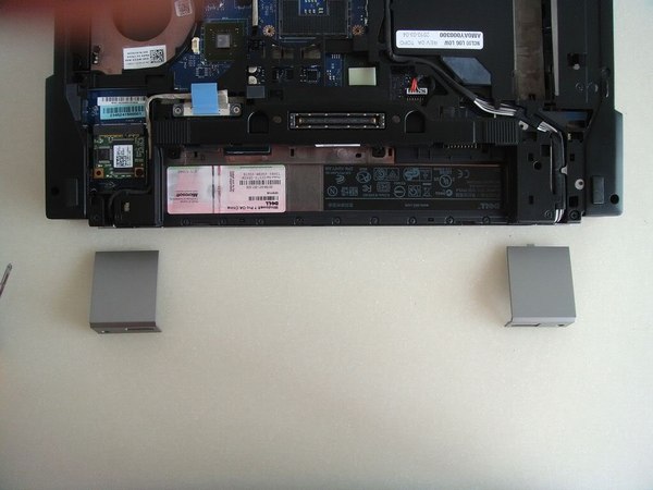
Remove two covers.
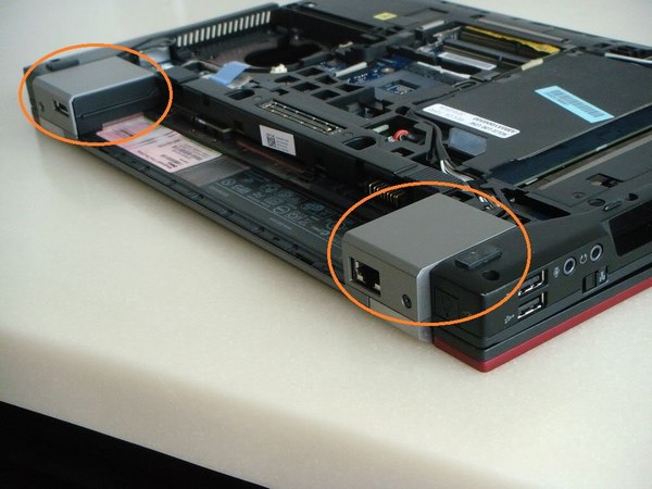
Under the cover, you can find two screws, remove it.
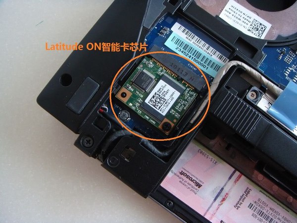
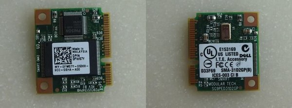
Remove one screw. You can remove the Latitude smart card.
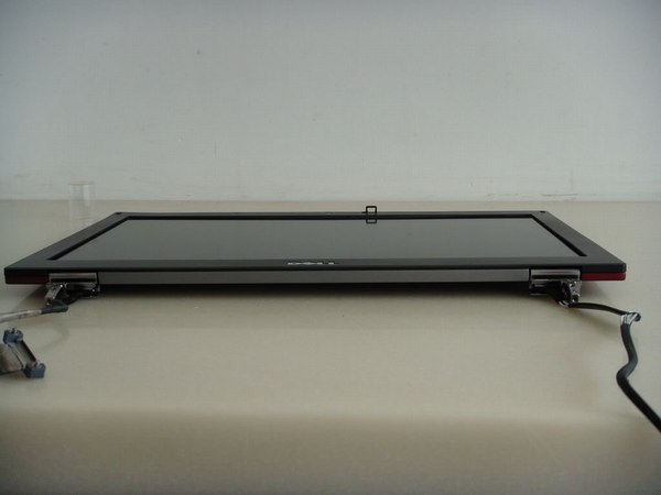
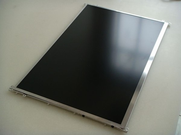
The LCD screen module has been removed.
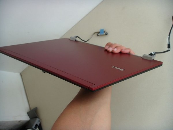
Remove the LCD bezel.
Remove the screws securing the LCD back cover.
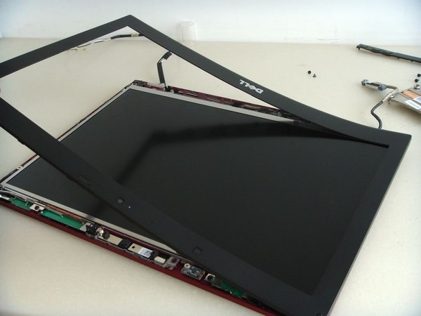
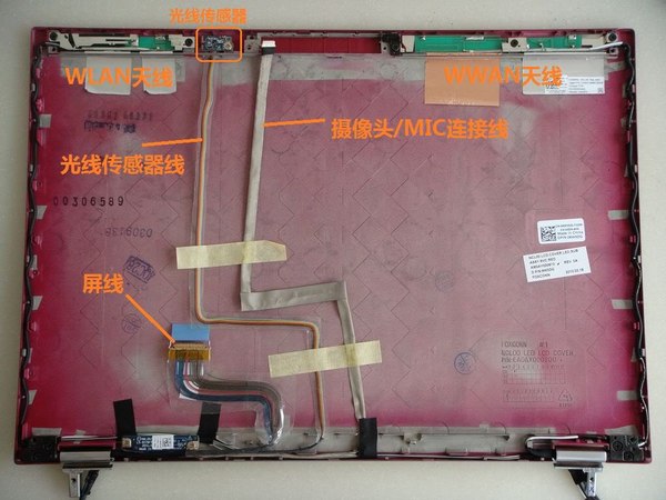
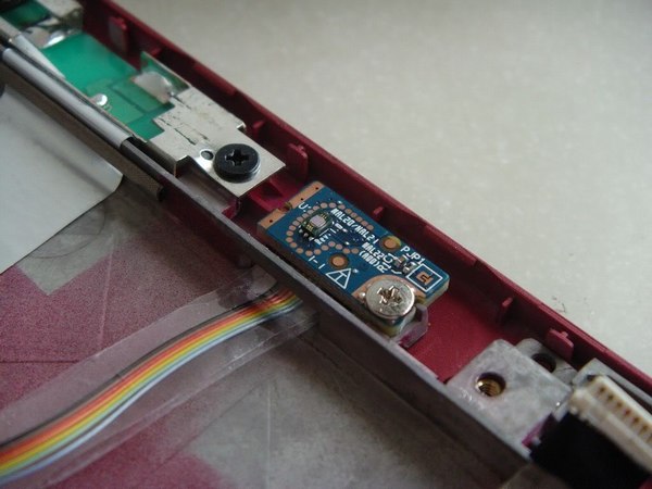
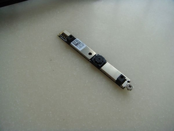
Now you can get access to the LCD cable and camera.
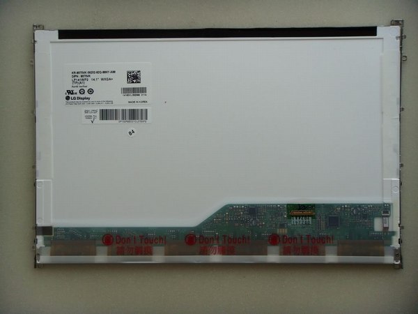
LG LP141WP2-TLB1, resolution: WXGA 1440X900.
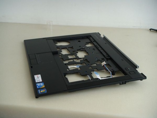
Remove three screws securing the palm rest and disconnect three cables. Pry up the palm rest.
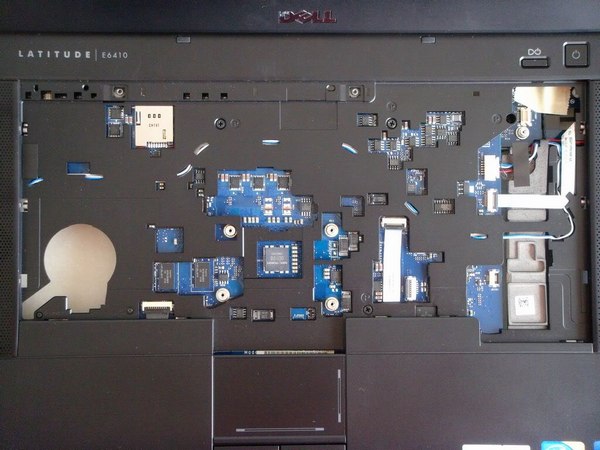
The palm rest has been removed.
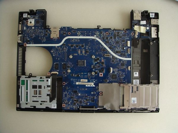
Remove the screws securing the motherboard.
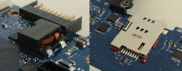
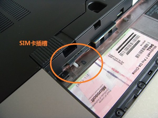
Battery connector and SIM card slot
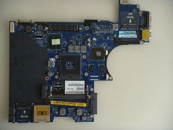
Dell Latitude E6410 motherboard
For more guides, check out the Dell Latitude E6410 device page.

Hi, I have a Dell E6410. I am putting it back together, and I do not remember where it goes. I can’t put it back together till I know.
Hope you can help me and email me.
Thank you so much, Merry Christmas